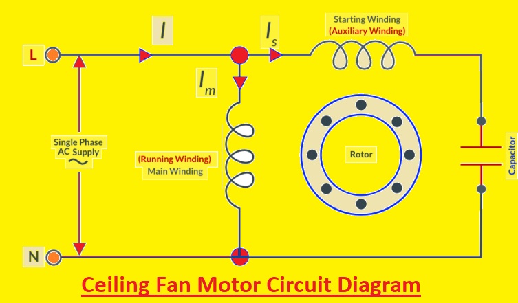
A ceiling fan that spins slowly, makes clicking noises, or refuses to start altogether often points to one common culprit: a failing capacitor. This small but essential component acts as the heart of your fan’s motor system, storing and releasing electrical energy to create the rotational force that powers the blades. When the capacitor fails, the entire fan malfunctions—yet many homeowners overlook this simple part during troubleshooting. Understanding how to diagnose, replace, and maintain your ceiling fan capacitor can save you both time and the cost of a professional service call.
The good news is that capacitor replacement ranks among the most DIY-friendly electrical repairs. With basic tools, a modest investment in a replacement part (typically $5-$15), and adherence to safety protocols, most homeowners can restore a non-working ceiling fan to full operation within an hour. This guide walks you through every step of the process, from recognizing failure symptoms to testing components and performing a safe replacement.
Identify Specific Capacitor Failure Symptoms
Pinpointing capacitor issues requires understanding the distinct malfunction patterns they create. Unlike other electrical problems, capacitor failures produce characteristic warning signs that help isolate the problem from motor or wiring issues.
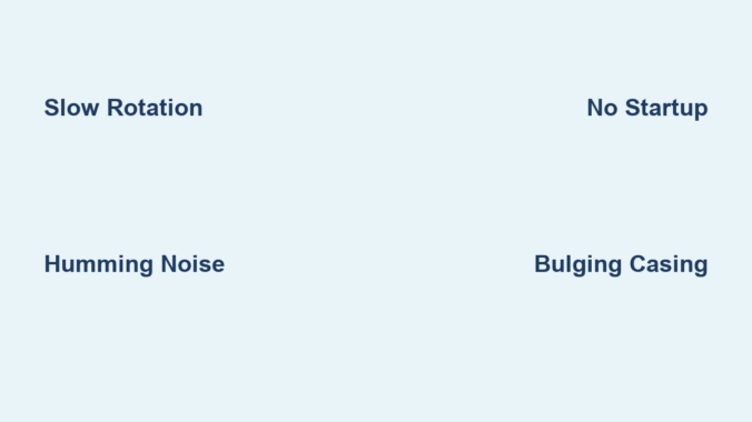
Slow or weak rotation at specific speeds reveals which capacitor section has failed. Ceiling fans with multiple speeds use capacitors with separate sections for each speed setting. If your fan spins normally on high but struggles on medium or low settings, the capacitor section dedicated to those speeds has degraded. The blades might take 5-10 seconds to reach half speed rather than accelerating smoothly.
Distinctive humming followed by clicking indicates a capacitor unable to maintain consistent power delivery. A healthy capacitor provides the motor with a steady electrical supply. When failing, it causes the motor to repeatedly attempt startup, creating a rhythmic “hum-click… hum-click” pattern every 2-3 seconds. This differs from a continuous buzz that might indicate motor bearing problems.
Single-direction operation failure points to issues with specific capacitor terminals. Many modern ceiling fans use dual-run capacitors where one section controls forward rotation and another handles reverse. If your fan works perfectly in one direction but won’t start in the other, the capacitor section dedicated to the non-working direction has failed.
Visible physical damage provides undeniable evidence of capacitor failure. Carefully inspect the component for bulging sides, ruptured vents, or oily residue leaking from the casing. A capacitor that appears swollen like a puffed pastry or shows brownish fluid stains has definitely failed and requires immediate replacement.
Safety Protocol for Capacitor Replacement

Proper safety preparation prevents electrical shock and ensures a successful repair. Many DIYers underestimate the dangers of working with capacitors, which can store lethal charges even when power is disconnected.
Implement a double-lockout power system by turning off both the circuit breaker and removing the fan’s pull chain. After switching off the breaker, remove the pull chain that controls the fan’s light or speed settings. This creates a physical barrier preventing accidental re-energizing while you work. Place the removed chain in your toolbox as a visual reminder that power is disconnected.
Verify complete de-energization using two separate testing methods. First, use a non-contact voltage tester on the fan housing and wiring connections. Then, confirm with a multimeter set to AC voltage across the capacitor terminals. Both tests must show zero voltage before proceeding. Test repeatedly throughout the process—capacitors can sometimes develop residual charges.
Create a safe work zone by clearing the area beneath the fan and securing your ladder. Place a soft blanket or drop cloth directly under your work area to catch any dropped screws or components. Ensure your ladder sits on a level surface and has rubber feet contacting solid flooring. Have a helper stabilize the ladder if possible, especially in rooms with high ceilings.
Wear appropriate protective gear including rubber-soled shoes, insulated gloves rated for electrical work, and safety glasses. These simple precautions prevent accidental contact with live components and protect your eyes from falling debris when removing the fan canopy.
Precise Capacitor Testing Methodology
Accurate testing determines whether replacement is truly necessary or if another component has failed. Many homeowners replace capacitors unnecessarily because they lack proper testing knowledge.
Perform an in-circuit resistance test before complete disconnection. With power confirmed off, set your multimeter to the highest ohms setting (typically 20MΩ). Touch one probe to the common terminal (usually labeled “C”) and the other to each speed terminal in turn. A functioning capacitor shows increasing resistance as it charges, eventually reaching infinity. A failed capacitor shows no resistance change or immediate zero resistance.
Conduct an out-of-circuit capacitance measurement for definitive results. After safely discharging the capacitor (by briefly shorting terminals with an insulated screwdriver), remove it from the circuit. Set your multimeter to capacitance mode and connect probes to corresponding terminals. Compare readings to the capacitor’s labeled value—anything more than 15% below specification indicates failure. For example, a 4.5µF capacitor reading below 3.8µF needs replacement.
Execute a voltage retention test to identify weak capacitors. Charge the capacitor by briefly connecting it to a 9V battery, then disconnect and measure voltage across terminals with your multimeter. A healthy capacitor maintains 80%+ of its initial voltage for 30+ seconds. One that drops below 50% within 10 seconds has degraded significantly and will fail soon.
Document all test results in a simple table format for reference:
| Test Type | Expected Reading | Actual Reading | Pass/Fail |
|———–|—————–|—————-|———–|
| In-Circuit Resistance | Gradual increase to ∞ | Immediate ∞ | Fail |
| Capacitance | 4.5µF ±10% | 3.7µF | Fail |
| Voltage Retention | >80% at 30s | 45% at 10s | Fail |
Streamlined Replacement Procedure
A systematic replacement approach minimizes errors and ensures proper installation. Following these precise steps takes most homeowners 20-40 minutes from start to finish.
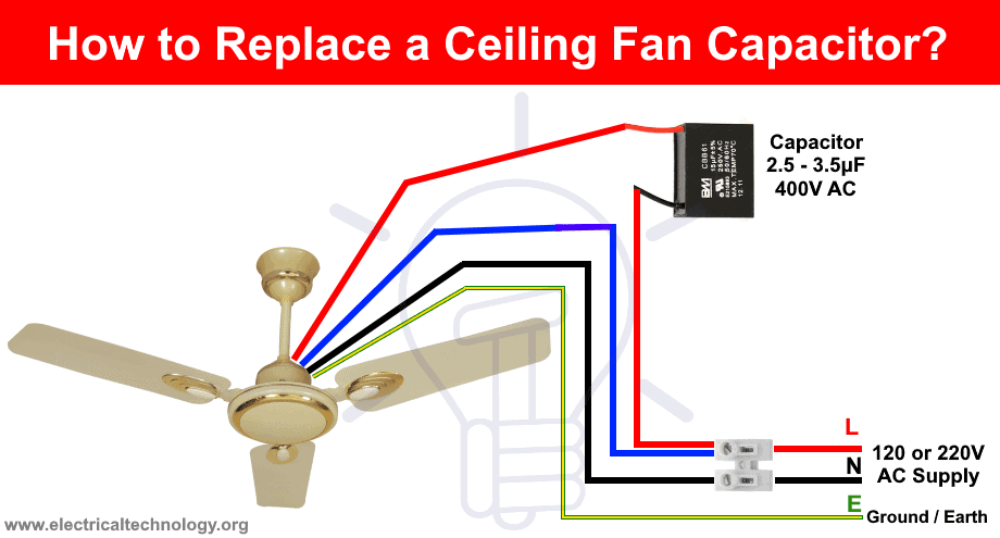
Label connections before disconnection using color-coded tags matching terminal designations. Purchase small wire markers (available at hardware stores) labeled “C,” “1,” “2,” and “R” corresponding to common, speed 1, speed 2, and reverse terminals. Slide these onto wires before removing them from the old capacitor. This eliminates guesswork during reinstallation.
Clean terminal connections before attaching to the new capacitor. Use a small wire brush or folded emery board to gently remove oxidation from both wire ends and capacitor terminals. This ensures maximum conductivity and prevents future connection issues. Apply a thin coat of electrical contact cleaner to each terminal for optimal performance.
Secure the new capacitor using the manufacturer’s mounting method. Most capacitors have a metal strap or plastic clip that attaches to the fan’s switch housing. Ensure the capacitor sits parallel to the mounting surface with terminals facing outward for easy access. Avoid twisting or bending the capacitor body during installation, as this can damage internal components.
Implement the “one wire at a time” replacement method to prevent cross-connections. Remove and reconnect each wire individually rather than disconnecting all at once. Complete the common wire connection first, followed by speed wires, and finally the reverse wire. Test each connection by gently tugging on the wire to ensure it’s secure before moving to the next.
Post-Replacement Verification Protocol
Thorough testing after installation confirms successful repair and identifies potential issues before they cause damage.
Conduct a graduated startup sequence beginning with the lowest speed setting. Allow the fan to run for 2 minutes at low speed before advancing to medium, then high. This gradual approach prevents electrical stress on the new capacitor and allows you to detect subtle problems at lower loads. Listen for smooth acceleration without hesitation or unusual noises.
Measure operational temperature after 15 minutes of continuous use. A properly functioning capacitor should remain cool to the touch—never exceeding 104°F (40°C). Use an infrared thermometer to check both the capacitor and motor housing. Temperatures above 122°F (50°C) indicate improper installation, incorrect capacitor specifications, or underlying motor problems.
Perform a vibration analysis by placing your palm lightly on the fan housing. A successfully repaired fan operates with minimal vibration—less than 0.1 inches per second on a vibration meter. Excessive vibration (more than 0.3 ips) suggests wiring errors or motor imbalance that requires further investigation.
Document baseline performance metrics for future reference. Note the exact startup time (should be 1-2 seconds from standstill), operational noise level (should be a quiet hum), and power consumption using a watt meter. These measurements help identify future problems by providing comparison points.
Proactive Maintenance Strategies
Implementing these simple maintenance practices extends capacitor lifespan by 30-50% and prevents premature failures.
Schedule seasonal capacitor inspections coinciding with daylight saving time changes. During these inspections, check for bulging, listen for unusual sounds at startup, and verify all speed settings function correctly. Early detection of minor issues prevents complete failures during peak usage seasons.
Install a thermal fuse as additional protection against overheating. Solder a 220°F (104°C) thermal fuse between the capacitor and motor leads. This inexpensive component (under $2) automatically disconnects power if temperatures exceed safe levels, preventing capacitor damage from overheating.
Apply dielectric grease to all electrical connections during replacement. This specialized grease prevents corrosion, improves conductivity, and creates a moisture barrier. Use sparingly—just enough to coat terminal surfaces—without getting grease on the capacitor body.
Monitor voltage stability in your home’s electrical system. Frequent voltage fluctuations (above 125V or below 110V) significantly shorten capacitor life. Consider installing a whole-house voltage regulator if your area experiences regular power surges or brownouts.
A failing ceiling fan capacitor doesn’t have to mean expensive professional service or fan replacement. By recognizing the specific symptoms, following proper safety protocols, and executing precise replacement techniques, you can restore full functionality to your ceiling fan with minimal investment. Remember that regular maintenance and prompt attention to early warning signs can extend your capacitor’s lifespan significantly, keeping your fan running smoothly for years to come. When performed correctly, this straightforward repair delivers immediate comfort improvements while saving you the cost of professional service calls.
Leave a Reply