Installing a ceiling fan with remote control capability transforms how you manage comfort in your home, but the wiring process presents challenges that trip up many DIY enthusiasts. The complexity isn’t in the fan itself—it’s in integrating modern wireless control systems with existing household electrical configurations. Whether you’re replacing an existing fan or tackling a new installation, understanding the wiring diagram for your ceiling fan remote system means the difference between a seamless upgrade and a frustrating project that leaves you calling an electrician.
The good news is that most ceiling fan remote installations follow predictable patterns once you understand the fundamental principles. This guide walks you through every configuration you’ll encounter, from straightforward single-switch setups to complex dual-switch integrations. You’ll learn exactly how to interpret wiring diagrams, avoid dangerous mistakes, and ensure your installation meets electrical code requirements. By the end, you’ll have the knowledge to tackle your installation with confidence—or at least communicate effectively with whoever does the work for you.
Remote System Components Overview
A ceiling fan remote system consists of two essential components that work together to give you wireless control over fan speed, lighting, and sometimes direction. The handheld transmitter is the remote you carry around the house, sending radio frequency signals to control your fan. The receiver module is the less visible but equally important component—it’s installed either within the fan assembly or sometimes in the ceiling electrical box, interpreting those signals and routing power to the appropriate fan functions.
The receiver module is where the real electrical work happens. Think of it as a traffic cop for electricity: it receives incoming power from your home’s wiring, processes the signals from your remote, and then distributes conditioned power to the fan motor and light kit based on what you want the fan to do. This architecture explains why proper wiring matters so much—the receiver expects power to flow in a specific direction, and violating that expectation creates both safety hazards and functional problems.
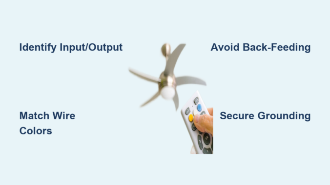
Understanding the difference between input and output connections on your receiver is crucial for any ceiling fan remote wiring diagram interpretation. The input side connects to your home’s electrical system and receives raw 120-volt power. The output side connects to the fan assembly, delivering controlled power to the motor and lights. Every wiring mistake that creates problems in remote installations ultimately traces back to confusing these two sides or connecting them incorrectly.
Single Switch Wiring Configuration
The simplest ceiling fan remote installation involves a single wall switch that previously controlled the entire fan and light assembly. In this configuration, the wall switch becomes essentially a master power disconnect, while the remote receiver handles all the nuanced control over speed and lighting. This setup works beautifully when you don’t need independent wall switch control of fan and light functions—the remote provides complete control anyway.
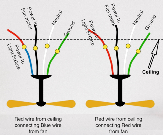
In this configuration, the wiring diagram is straightforward. The incoming hot wire from your ceiling connects to the input side of the remote receiver. All the neutral wires bundle together—the white from the ceiling, the white input on the receiver, and the white wire from the fan assembly. The output wires from the receiver then connect to the fan motor and light kit, with black typically controlling the fan and blue controlling the lights.
Pro Tip: This installation typically takes 30-45 minutes for experienced DIYers. Look for matching wire colors between your receiver and fan assembly—most manufacturers follow standard color conventions. If you see a yellow wire, it likely controls direction reversal on Hunter fans.
The wall switch in this setup serves one critical purpose: it ensures the fan system can be completely de-energized when you’re not using it. When the switch is off, no power reaches the receiver, so the remote can’t activate the fan. When the switch is on, the receiver has power and can respond to remote commands. This arrangement is safe, code-compliant, and remarkably simple once you understand which wires go where.
Dual Switch Integration Solutions
The dual switch configuration is where most ceiling fan remote installations get complicated. If you have two separate wall switches that originally controlled the fan motor and light kit independently, you’re dealing with a dual-switch setup, and integrating remote control requires careful planning to maintain functionality while adding wireless capability.
The fundamental challenge is that a standard remote receiver needs to be the intermediary for all controlled functions. When two switches already control different aspects of the fan, you have to decide which switch provides power to the receiver and what happens to the other switch. The most common approach dedicates one switch to power the receiver while the other switch becomes non-functional or controls a different circuit entirely. This sacrifices independent wall control but enables full remote functionality.
Why Your Dual Switch Installation Fails
Many homeowners encounter problems because they try to preserve both wall switches while adding remote control. This almost always creates dangerous back-feeding conditions. When you connect a wall switch to the output side of the receiver (between receiver and fan), you’re reversing the expected power flow. This might work temporarily but creates serious shock hazards and will eventually damage your receiver.
Feasibility depends heavily on what wires exist in your ceiling electrical box. Homes wired with 12-3 or 14-3 cable (containing black, red, and white conductors) provide the flexibility for various configurations because you have separate conductors for fan and light circuits. Homes with only 12-2 or 14-2 cable (black, white, and ground) lack the extra conductor needed for true independent control and limit your options. Before starting any dual-switch integration, examine what’s in your ceiling box to understand what you’re working with.
Wire Color Conventions Explained
Mastering wire color conventions is essential for interpreting any ceiling fan remote wiring diagram correctly. These colors aren’t arbitrary—they follow established conventions that tell you what each wire does in the electrical system. Understanding them prevents dangerous mistakes and helps you diagnose problems when things don’t work as expected.
Black wires carry ungrounded (hot) current through your electrical system. In ceiling fan installations, black wires might be incoming power from the ceiling, switched power to the fan motor, or even travelers in multi-switch configurations. The key is to trace each black wire to understand its specific function rather than assuming all black wires are equivalent.
White wires serve as grounded (neutral) conductors, providing the return path for current in properly functioning circuits. In ceiling fan remote installations, neutral connections are critical for the receiver’s electronics to operate. You’ll typically bundle three white wires together: one from the ceiling, one going to the receiver input, and one from the fan assembly.
Green and bare copper wires provide equipment grounding, connecting accessible metal parts to the building’s grounding system. These wires should always connect together and to any grounding screws or metal boxes in the installation. Never ignore grounding connections—they protect you from shock hazards if something goes wrong.
Blue wires in ceiling fan assemblies specifically control lighting circuits, while yellow wires may indicate secondary speed controls or direction reversal functions depending on the manufacturer. Red wires commonly serve as switched hot conductors in dual-switch configurations, carrying power from one switch to the load. Always consult your specific fan’s documentation, as wire functions can vary between manufacturers.
Essential Safety Precautions
Electrical work carries real risks that demand respect. Before touching any wires for your ceiling fan remote installation, turn off power at the circuit breaker and verify the power is actually off using a non-contact voltage tester. This isn’t optional—contact with live electrical conductors can result in severe injury or death. Test at both the ceiling electrical box and any wall switch locations to confirm all related circuits are de-energized.
The testing process should become habit before you touch any wire. Even if you turned off what you believe is the correct breaker, verify with a tester. Breakers are sometimes mislabeled, and assumptions about which circuit controls which fixture have led to electrocutions. A $20 voltage tester is one of the most important tools you can own for electrical work and might save your life.
Beyond the immediate shock hazard, improper electrical installations create long-term dangers. Loose connections generate heat that can damage equipment and ignite fires. Back-feeding current through receiver output terminals creates shock hazards that may not manifest immediately but exist regardless. Code requirements exist because someone learned the hard way that certain practices are dangerous—following those requirements protects you and future occupants of your home.
Step-by-Step Installation Process
Beginning your ceiling fan remote installation requires methodical preparation before you touch a single wire. Start by gathering your tools: a voltage tester, wire strippers, screwdrivers, and wire nuts in various sizes. Having everything within reach prevents shortcuts that lead to mistakes. Read through your fan’s installation instructions and your remote receiver’s documentation before starting—different manufacturers may have specific requirements that apply to their equipment.
With power confirmed off at the breaker, remove the existing fan or fixture from the ceiling electrical box. Take photographs of the existing wire connections before disconnecting anything—these images provide invaluable reference when reconnecting everything. Note which wires connected to which terminals and how the grounding was configured. This documentation is especially critical if you’re working with a complex dual-switch setup.
Critical Grounding and Neutral Connections
-
Grounding first: Connect all bare or green grounding conductors together: the ground from the ceiling, the ground on the receiver module, and the ground from the fan assembly. Twist these together securely and cap with an appropriate wire nut.
-
Neutral connections next: Bundle the white wire from the ceiling, white input wire on the receiver, and white wire from the fan assembly. If your receiver has dual white wires labeled “to ceiling” and “to fan,” connect accordingly.
-
Hot input connection: Connect the black wire from the ceiling to the black input wire on the remote receiver. This conductor provides the incoming power that runs the receiver’s electronics.
-
Output connections: Connect the black output wire from the receiver to the black wire in the fan assembly (controls fan motor). Connect the blue output wire from the receiver to the blue wire in the fan assembly (controls light kit).
Double-check all connections before restoring power. A single misplaced wire can damage your receiver or create dangerous conditions. After power restoration, test the remote at various distances to verify proper operation.
Avoiding Back-Feeding Hazards

Back-feeding represents one of the most dangerous and unfortunately common mistakes in ceiling fan remote installations. This practice involves connecting a wall switch to the wires between the receiver output and the fan assembly, allowing power to flow in the opposite direction the receiver circuitry expects. It might appear to work—some installations function for years before failing—but the hazards are real regardless of whether problems have manifested.
Why back-feeding is always dangerous:
– Receiver electronics are designed for one-way power flow
– Creates shock hazards at switch locations
– Violates electrical code requirements
– Will eventually damage the receiver module
Professional electricians never install receiver systems with back-feeding, and manufacturer instructions never specify this configuration. The absence of immediate failure doesn’t indicate safety—it indicates that a hazard exists without yet having produced visible consequences. Electrical safety organizations consistently warn against this practice because they’ve seen the injuries and property damage that result when the hazard finally manifests.
If your current installation involves back-feeding, correct it immediately even if it appears to work. The risk isn’t worth the convenience of maintaining switch functionality. Safe alternatives exist that provide the control you want without the hazards back-feeding creates.
Brand-Specific Wiring Notes
Hampton Bay universal remote systems, particularly the Model # 191-707, use a receiver designed for ceiling installation rather than wall switch mounting. The receiver has three wires connecting to the fan assembly (black-blue-white configuration) and two wires connecting to AC power (white-black). The control unit sends commands through the power wiring itself rather than radio frequency, eliminating the need for a separate signal conductor. This design affects how you integrate it with existing switch configurations.
Hunter ceiling fans with remote capability use receiver modules with wire configurations that differ from universal systems. Successful integration often requires specific wire mapping that preserves some wall switch functionality while enabling remote control. Documentation from the installation date becomes critical when maintaining or replacing these systems years later.
Lutron offers an alternative approach that some homeowners prefer: fan switches and light dimmers installed without remote receivers. This approach eliminates the receiver module entirely while preserving independent wall control of fan speed and light intensity. The tradeoff is losing remote control capability, though some Lutron systems offer smart home integration that provides app-based control as an alternative.
Maintenance Tips for Reliable Operation
Periodic inspection of your ceiling fan remote system catches potential problems before they become dangerous. Annually, turn off power at the breaker and remove the fan canopy to inspect all wire connections. Check for signs of overheating—discoloration, melting, or burned smells indicate problems that need immediate attention. Tighten any connections that have worked loose due to vibration.
The remote control battery deserves proactive replacement even before it fails completely. Mark your calendar to replace the battery every twelve months as preventive maintenance. This eliminates the surprise of a dead battery at an inconvenient moment and ensures reliable remote operation when you need it.
Keep the remote control itself clean and protected. Button contacts can accumulate debris that affects reliability, and dropped remotes can suffer internal damage that isn’t visible from the outside. If your remote shows physical damage or has been dropped, consider replacing it rather than risking intermittent operation at an inconvenient time.
Key Takeaways for Successful Installation
Understanding the fundamental principles behind ceiling fan remote wiring diagrams transforms a confusing project into a manageable task. The receiver module has specific input and output sides that must be respected—power enters on the input side and exits on the output side to controlled loads. Violating this distinction creates both immediate hazards and long-term reliability problems that cost more to fix than doing it right the first time.
Single-switch configurations are straightforward and work well for most applications. Dual-switch configurations require careful planning and may involve sacrificing some wall switch functionality to achieve safe remote integration. Always verify what’s in your ceiling electrical box before purchasing equipment, as older homes with limited wiring options face more constraints.
Safety should never be compromised for convenience. If a configuration requires back-feeding or other unsafe practices, it isn’t a valid solution regardless of how well it might appear to work. Licensed electricians exist precisely because electrical mistakes can kill people, and there’s no installation worth risking your life over.
Leave a Reply