If your workshop or garage needs powerful ventilation, a Canarm exhaust fan is a top-tier solution. But before it starts pulling out fumes and freshening the air, you need to wire it correctly. Whether you are installing a P1107-F, P1170 CG, or another single-phase model, improper wiring can lead to motor failure, safety hazards, or no operation at all. This guide walks you through every step, from identifying voltage requirements to connecting wires safely and testing the unit.
You will learn exactly how to wire a Canarm exhaust fan for 115V or 230V systems, interpret color-coded leads, and avoid common mistakes that damage motors. Let us get your fan running safely and efficiently.
Identify Your Canarm Fan Model and Voltage Requirements
Before touching any wires, confirm your Canarm exhaust fan model and required voltage. Most units like the P1107-F and P1170 CG support dual-voltage operation, but they must be wired specifically for your supply.
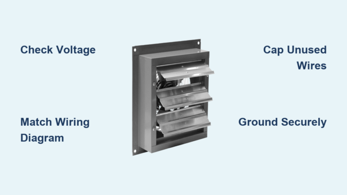
Locate the Motor Wiring Diagram
Find the wiring diagram on the motor housing. This label shows acceptable voltage, wire grouping instructions, and terminal numbers. Look for two diagrams: one for low voltage on the left side and one for high voltage on the right side. Always match your supply voltage to the correct diagram.
Verify Your Power Supply
Use a multimeter to test your circuit before connecting anything. For 115V systems, you need one hot wire (black), one neutral wire (white), and a ground wire. For 230V systems, you need two hot legs (black and red) plus ground, with no neutral used. Never assume your outlet type matches the correct voltage without verifying first.
Match Your Model to the Correct Wiring Type
Different Canarm models use different connection methods. The P1107-F uses loose colored leads that require manual grouping. The P1170 CG uses numbered terminal posts for simpler connections. Some models like the XFS12 come with a plug (NEMA 5-15P) and require no hardwiring at all.
Wire the Canarm P1107-F Motor for 115V or 230V
The P1107-F uses individual colored wires that must be grouped based on your voltage selection. Incorrect grouping can burn out the motor immediately, so follow these steps precisely.
Connect the P1107-F for 115V Single-Phase Operation
This configuration uses a neutral wire and is common in residential workshops.
Attach Line 1 (Hot) to P1
Connect the black circuit wire (hot) to the P1 terminal on the motor. Use a wire nut or appropriate terminal connector to secure the connection firmly.
Join Black, White, and Yellow Wires to Neutral
Twist together the motor black, white, and yellow leads. Connect this group to the Line 2 (neutral/white circuit wire). Strip one-half inch of insulation and use a UL-listed wire nut. Tug each wire after connecting to ensure security.
Cap Off P2 and Orange Wire Together
Twist the P2 lead and orange lead together, then insulate with a wire nut. Do not connect this group to any power source.
Insulate All Remaining Unused Leads
Any wires not specifically mentioned should be capped individually. Tuck them neatly into the junction box to prevent accidental contact with terminals or metal parts.
Connect the P1107-F for 230V Single-Phase Operation
In 230V mode, both lines are hot and no neutral is used. This configuration is typical for heavy-duty commercial applications.
Attach Line 1 (Hot) to P1
Connect the circuit black wire to P1 on the motor. This serves as the primary hot input.
Link Black and Yellow to Line 2 (Hot)
Twist the motor black and yellow leads together. Connect this group to the second hot leg (red circuit wire).
Isolate Red, Orange, and White Leads
Group the red, orange, and white motor leads together and cap them with a wire nut. These windings are not used in 230V operation.
Cap P2 Alone
The P2 lead must be capped off by itself. Do not connect it to any other wire or terminal.
Warning: In 230V mode, never connect anything to neutral. Doing so creates a direct short circuit that can damage the motor or trip breakers.
Wire the Canarm P1170 CG Motor Using Terminal Posts

The P1170 CG simplifies wiring by using numbered terminals instead of loose leads. This reduces confusion and makes connection more straightforward.
Use Terminals 1 and 4 for Power in Both Voltage Configurations
Both 115V and 230V setups use the same two terminals. Only the power source connection changes.
For 115V Operation: Hot and Neutral
Connect L1 (hot) to Terminal 1. Connect L2 (neutral) to Terminal 4. Attach the ground wire to the grounding screw on the motor housing.
For 230V Operation: Two Hot Legs
Connect L1 (hot) to Terminal 1. Connect L2 (hot) to Terminal 4. The motor does not distinguish neutral from hot. It simply sees the voltage difference between the two terminals.
Ground the Motor Housing Properly
Locate the green grounding screw on the motor frame. Attach the bare copper or green circuit wire. Loop the wire clockwise around the screw for better grip, then tighten securely. After connection, tug the wire gently to confirm it will not pull out.
Understand Five-Wire Color Codes for Multi-Speed Fans

Some Canarm fans include five wires: black, white, yellow, blue, and brown. These indicate multi-speed or capacitor connections that require proper identification.
Decode Each Wire Function
The black wire serves as the main power input and is always connected. The white wire carries neutral in 115V systems only. The yellow wire connects to the capacitor or start winding and is critical for startup. The blue wire provides the medium speed tap on three-speed models. The brown wire offers the low speed tap when used with pull-chain switches.
Test Wire Functions with a Multimeter
Set your multimeter to resistance (Ω) mode. Test between pairs of wires to identify winding connections. The highest resistance reading typically indicates the start winding (often yellow combined with black). The lower resistance indicates the run winding. Match your findings to the manufacturer diagram.
Follow Critical Safety Protocols Before Wiring
Electric shock and motor damage are real risks. Follow these safety steps every time you work on your Canarm fan.
Turn Off Power at the Breaker
Switch off the circuit breaker supplying power to the fan location. Apply Lockout/Tagout (LOTO) procedures if working in a commercial setting. Test all wires with a non-contact voltage tester before touching any conductors. Never rely on a wall switch alone to ensure power is off.
Inspect Wires and Junction Box
Check all wiring for frayed insulation, burns, or corrosion. Ensure the junction box is dry, accessible, and code-compliant. Use a weatherproof box if installing outdoors or in damp areas like workshops.
Use Proper Tools and Personal Protective Equipment
Wear insulated gloves and safety glasses during all electrical work. Use wire strippers designed for the gauge you are working with. Choose only UL-listed wire nuts or lever connectors. Keep a fire extinguisher rated for electrical fires nearby throughout the project.
Install a Code-Compliant Junction Box
All connections must be enclosed in an accessible junction box that meets electrical codes.
Choose the Right Box
Select a minimum 4-inch by 4-inch by 1.5-inch box for most fan installations. Both metal and PVC boxes are acceptable if properly rated. The box must allow full access without removing the fan from its mounting position.
Mount the Box and Route Wires
Mount the junction box as close to the motor as possible. Keep wire runs short and direct. Use clamps or strain reliefs where wires enter the box to prevent damage from vibration.
Seal Against Moisture
Use grommets or bushings on knockout entries. Apply silicone sealant around outdoor box seams. Ensure the lid seals tightly. For outdoor installations, use a rainsafe cover with drip loop wiring.
Test the Fan After Wiring
Never assume the fan works correctly. Verify every connection before finalizing the installation.
Perform a Visual Inspection First
Check that all wire nuts are tight and secure. Look for any exposed copper that could cause shorts. Confirm the ground connection is solid. Ensure wire management is neat with no pinched or compressed conductors.
Conduct a Continuity Test
With power still off, set your multimeter to continuity mode. Test between Line 1 and P1 (should beep). Test between Line 2 and the neutral group for 115V setups. Verify no continuity exists between any wire and the motor housing, which would indicate a short.
Power Up and Observe
Restore power at the breaker. Turn on the switch. Watch for immediate startup and smooth rotation. Listen for abnormal sounds like grinding or humming. Smell for any burning or smoke. If the motor hums but will not start, the capacitor or start winding is likely faulty.
Confirm Proper Rotation Direction
Stand behind the fan. The blades should move away from the motor housing. If rotation is reversed, swap the two power leads (only if your specific model allows reversal).
Troubleshoot Common Wiring Problems
Even careful work can encounter issues. Use this guide to diagnose problems quickly.
Fan Does Not Start
Possible causes include incorrect wire grouping, an open circuit from a loose connection, or a tripped breaker. Recheck all diagrams and connections. Test voltage at the source. Ensure every wire nut is tight and making proper contact.
Motor Hums but Will Not Run
This typically indicates a failed start capacitor or a disconnected yellow wire. Test the capacitor with your multimeter (should read 8-12 µF). Replace if bulging, leaking, or outside the range. Confirm the yellow wire connects per the diagram.
Breaker Trips Immediately
This usually means a short circuit, ground fault, or miswired 230V setup with neutral connected. Disconnect power and inspect for pinched wires or exposed copper. Verify no neutral wire connects in 230V configurations.
Motor Overheats During Operation
Causes include wrong voltage applied to the motor, high resistance in loose connections, or poor ventilation around the fan. Confirm your supply voltage matches the motor requirements. Tighten all terminals. Ensure the fan is not blocked or surrounded by insulation.
Maintain Your Canarm Fan for Long-Term Performance
Proper wiring is just the beginning. Long-term performance depends on regular maintenance.
Clean Blades and Louvers Annually
Turn off power before cleaning. Wipe blades with a damp cloth to remove dust buildup. Remove debris that forces the motor to work harder. For magnetic louver models, ensure louvers close fully when the fan is off.
Inspect Wiring Yearly
Check for loose terminals that may have vibrated loose. Look for heat discoloration on wires and connectors. Replace any cracked wire nuts or damaged insulation immediately.
Never Lubricate the Motor
Canarm motors are permanently sealed. Adding oil damages internal bearings and attracts dirt. Do not drill lubrication holes. You will void the warranty and potentially destroy the motor.
Key Takeaways for Wiring Your Canarm Exhaust Fan
Wiring a Canarm exhaust fan correctly ensures safety, efficiency, and long motor life. Whether connecting a P1107-F with loose leads or a P1170 CG with terminals, always match your voltage configuration precisely, use a code-compliant junction box, ground the motor properly, and test thoroughly before full operation. For plug-in models like the XFS12, no wiring is required, but proper mounting and sealing remain essential. When in doubt, consult a licensed electrician. Your workshop air quality and your safety depend on correct installation.
Frequently Asked Questions About Wiring Canarm Exhaust Fans
Can I wire my Canarm fan for 230V if my workshop has 115V power?
No. The motor must match your available supply voltage. Wiring a 115V motor to 230V will destroy it immediately. Conversely, wiring a 230V motor to 115V will cause it to run poorly or not start at all. Always verify your supply voltage before purchasing or wiring a fan.
What happens if I do not ground my Canarm exhaust fan?
Skipping the ground connection creates a serious shock hazard. If a wire shorts to the motor housing, the metal frame could become energized. Grounding ensures the circuit trips the breaker quickly if a fault occurs. Proper grounding is required by electrical codes and essential for safety.
How do I know if my P1107-F is wired correctly for 230V?
In 230V mode, P1 connects to one hot leg. The black and yellow motor leads connect together to the second hot leg. P2 is capped off alone. The red, orange, and white leads are capped together. No neutral wire should be connected to the motor in a 230V configuration.
Can I use my Canarm fan with a speed control switch?
Yes, if your model supports multi-speed operation. Fans with five-wire configurations (black, white, yellow, blue, brown) include speed taps. Connect the blue wire for medium speed or the brown wire for low speed. Always verify against the manufacturer wiring diagram before connecting speed controls.
Why does my fan hum but not start when I turn it on?
This usually indicates a failed start capacitor or a disconnected yellow wire (start winding). Test the capacitor with a multimeter set to capacitance mode. It should read approximately 8-12 microfarads. Replace if the reading is outside this range or if the capacitor shows physical damage.
Leave a Reply