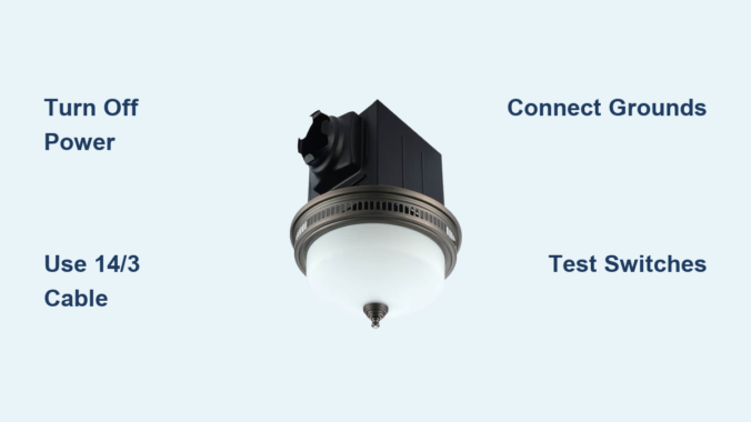
Wiring a bathroom exhaust fan with light can feel intimidating, but with the right guidance, it is a manageable DIY project that improves comfort, air quality, and energy efficiency. Whether you are replacing an old unit or installing one for the first time, understanding how to wire the fan and light, especially with single or dual switches, is essential for safe, code-compliant operation. This guide walks you through every step, from choosing the correct cable and tools to grounding, connecting wires, and testing your setup.
Understanding Single-Switch vs Dual-Switch Wiring for Bathroom Fans
Your wiring method depends on how you want to control the fan and light. A single-switch configuration simplifies wiring because both fan and light turn on and off together. This works well for smaller bathrooms where simultaneous operation is acceptable. A dual-switch configuration offers greater flexibility, allowing you to run the fan without the light or keep the light on without the noise. This is ideal for bathrooms used at night when you want ventilation without bright lighting, or during the day when you need airflow without illumination.
Selecting the Correct Cable Type for Your Setup
Use the appropriate cable based on your switch configuration. For single-switch control, use 14/2 with ground wire. This cable provides the hot, neutral, and ground conductors needed to power both fan and light from one switch. For dual-switch control requiring independent operation, use 14/3 with ground wire. The additional red conductor serves as the second switched hot, allowing separate control of the fan and light. For 20-amp circuits, upgrade to 12/2 or 12/3 respectively, matching the wire gauge to your breaker size.
Essential Tools and Materials for Wiring a Bathroom Exhaust Fan
Required Tools
Collect these tools before starting your installation. A voltage tester confirms power is off before you begin working. Wire strippers remove one-half inch of insulation cleanly without damaging conductors. Needle-nose pliers twist wires and handle connectors in tight spaces. A screwdriver set includes both Phillips and flathead options for securing connections. A cable ripper or utility knife opens sheathing without damaging the wires inside.
Required Materials
Gather these materials for a complete installation. Wire connectors include standard wire nuts or WGO lever nuts, which are easier to disconnect later. Cable clamps secure cables entering the boxes. Grounding pigtails bond ground wires to switches and fixtures. Dual rocker switches or two single-pole switches provide independent control. Electrical tape insulates switch bodies when installed in metal boxes.
Critical Safety Steps: Turning Off Power Before Wiring
Shutting Off the Circuit
Begin by turning off the breaker controlling the bathroom circuit. Test the wires at both the switch location and the ceiling box using a non-contact voltage detector. Confirm no power is present on black, white, or red wires before touching any conductors. Never assume the power is off based on breaker position alone. A single mistake can lead to serious injury.
Labeling the Breaker
Place tape over the breaker with a note reading “Bathroom Fan, Do Not Turn On.” This prevents accidental re-energizing while you are working. Have someone else in the household understand that the circuit should not be touched until you confirm the work is complete.
Installing the Junction Box and Running Cable
Box Size and Placement
Use a remodel box if working above existing drywall. Ensure the box volume meets NEC 314.16(B) requirements by calculating based on wire count. Each 14 AWG wire requires 2.0 cubic inches of space. Ground wires count as one wire total. Each device such as a switch counts as two wires. Cable clamps count as one wire each. For example, a dual-switch metal box with two 14/3 cables needs at least 21.0 cubic inches.
Securing the Cable
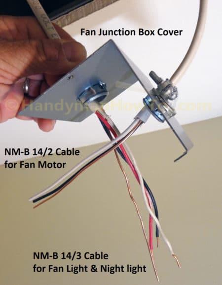
Feed the 14/3 cable from the switch box to the fan location. Use cable clamps to secure wires inside each box. Leave 6 to 8 inches of slack in both boxes for easy connections. Never stretch wires tightly because slack prevents strain on terminals during installation and future maintenance.
Ceiling Box Wiring: Connecting Fan and Light Wires
Connecting Ground Wires
Join all bare copper ground wires with a wire nut. Add a ground pigtail and connect it to the green grounding screw on the fan housing. Wrap the wire clockwise around the screw and tighten securely. All metal parts must be grounded, and even plastic-housed fans require fixture grounding for safety.
Joining Neutral Wires
Connect all white neutral wires together. This includes the source neutral from the cable, the fan neutral, and the light neutral. Use a three-conductor lever nut or wire nut for a secure connection. Neutrals are never switched; they run straight through to the fixture regardless of switch position.
Connecting Hot Wires by Configuration
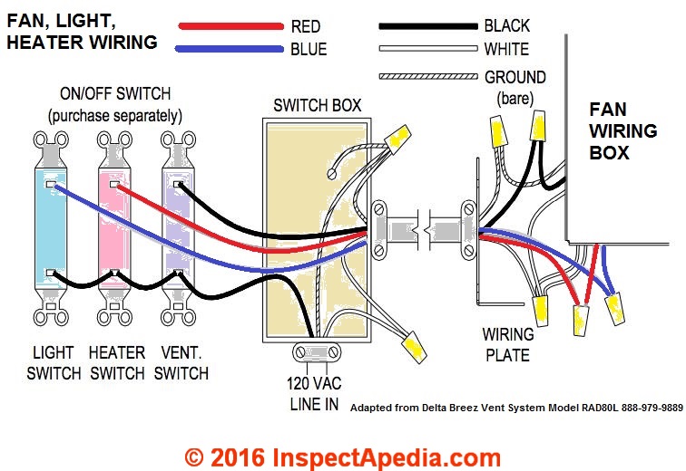
For a single-switch setup, the incoming black switched hot connects to both the fan black wire and the light blue wire. Use a wire nut to join all three conductors. The result is one switch that powers both devices simultaneously.
For a dual-switch setup, connect the black wire from the cable to the fan black wire. Connect the red wire from the cable to the light blue wire. Use separate two-conductor lever nuts for clean, reliable connections. Keep all connections tight and insulated because exposed copper can cause short circuits.
Switch Box Wiring: Connecting Power and Switches

Feeding Power to the Switch
Most bathroom fan circuits receive power at the switch box. The incoming 14/2 cable brings constant power with black as hot, white as neutral, and bare copper as ground.
Grounding All Components
Join the incoming ground, the cable ground going to the fan, and the metal box ground if applicable. Attach a pigtail to the green terminal on each switch. Metal boxes must be bonded to the grounding system for safety.
Tying Together Neutrals
Connect all white wires with a wire nut even if the switches do not use them. This is required by NEC 2011 and later for smart switch compatibility. Never cap off the neutral; leave it connected and accessible for future upgrades.
Distributing Constant Hot
Connect the incoming black constant hot to both switches. Use a pigtail, which is a short 6-inch black wire, to feed both switches from one source. Alternatively, connect to a common terminal if using a dual rocker switch. Secure all connections with screw terminals.
Connecting Switched Hots
Connect the red wire going to the light to the top terminal of one switch to control the light. Connect the black wire going to the fan to the bottom terminal of the second switch to control the fan. Label terminals with tape if they are not clearly marked. Wrap the switch body in black electrical tape if installing in a metal box to prevent accidental contact.
Completing Connections and Mounting Your Fan Unit
Tuck Wires Neatly
Fold all wires into the box without pinching them. Ensure no bare copper is exposed beyond the wire nuts. Proper wire management prevents damage and makes final assembly easier.
Mount the Fan Unit
Secure the fan housing to the joists or mounting brackets. Attach the grill and light cover. Install bulbs or LEDs if they are not pre-installed. Do not overtighten screws because plastic housings can crack under pressure.
Testing Your Installation: Restoring Power and Verifying Function
Turning On the Breaker
Double-check all connections before restoring power. Turn the breaker back on at the panel.
Testing Each Switch
Test the top switch, which should turn on the light only. Test the bottom switch, which should turn on the fan only. Try all combinations including light on with fan off, fan on with light off, both on, and both off. All combinations should function correctly.
Fixing Common Issues
If the light does not work, check for a loose red or blue wire connection at both the switch and the fixture. If the fan does not run, verify the black connection or test the motor. If both devices are dead, check for a tripped breaker or loose hot wire. If the wrong device turns on, swap the red and black wires at either the switch or the fixture. If you hear a buzzing sound, tighten all connections and confirm the switch is a standard switch, not a dimmer, because exhaust fans require standard switches.
Electrical Code Compliance and Safety Best Practices
NEC Compliance Checklist
Ensure the neutral wire is present in the switch box, which is required since 2011. Ground all metal parts including fixtures, boxes, and switches. Keep all junction boxes accessible with no buried splices. Calculate correct box fill based on wire and device count. Secure all cables within 8 inches of the box per NEC 314.17(C).
Safety Tips
Always turn off power at the breaker before touching any wires. Use lever nuts for reliable, tool-free connections. Label your switches after testing to identify which controls the fan and which controls the light. Install a GFCI breaker if an outlet is present in the bathroom, though this is not required for fan-only circuits.
Troubleshooting Common Bathroom Fan Wiring Issues
No Power? Check These First
Start by checking if the breaker has tripped and reset it if needed. Inspect for a loose neutral connection in the white wire bundle. Verify that the ground wire is properly bonded. Test the switch for continuity to confirm it is functioning.
Verifying with a Multimeter
Test voltage between black and ground, which should read approximately 120 volts. Test the switched red and black wires at the fan box with the switch in the on position. Confirm neutral continuity with ground, which should show as open.
Practical Example: Wiring a Commercial Electric 7132-12-CE Fan

This popular fan and light combination features an 80 CFM quiet fan rated at 1.5 sones, an adjustable white LED with color temperatures ranging from 3000K to 5000K, and a night light feature. The blue wire controls the light, the black wire controls the fan, and the white wire is neutral.
Run 14/3 cable from the dual switch location to the ceiling. At the ceiling box, connect all grounds together with a pigtail to the green screw. Tie all white neutrals together. Connect the black cable wire to the fan black wire. Connect the red cable wire to the light blue wire. At the switch box, connect the constant hot pigtailed to both switches. Connect the red wire to the top switch controlling the light. Connect the black wire to the bottom switch controlling the fan. Tie all neutrals together and bond all grounds with a pigtail. The result is full independent control that is code-compliant and operates quietly.
Maintenance Tips to Prevent Future Wiring Issues
Regular Upkeep
Clean fan blades and grille every six months to maintain airflow and prevent dust buildup. Replace bulbs as needed, noting that LEDs last significantly longer than incandescent bulbs. Check for loose wires during cleaning sessions. Listen for unusual noises that could indicate motor wear or mounting issues.
Upgrade Ideas
Consider replacing standard switches with timer switches such as the Lutron Maestro for automatic shutoff. Install a humidity sensor switch that activates the fan based on moisture levels. Use smart switches with app control, ensuring your box has both neutral and ground wires required for smart switch operation.
Key Takeaways for Successfully Wiring Your Bathroom Exhaust Fan
Remember these fundamental wiring rules. Neutrals always connect together and are never switched. Ground all metal parts for safety. For single-switch setups, use 14/2 cable and connect black to both fan and light. For dual-switch setups, use 14/3 cable with black for the fan and red for the light. The switch box must have a neutral wire present, which is an NEC 2011 requirement. Junction boxes must remain accessible, never bury splices. Always turn off power at the breaker and test before touching any wires. Test each function separately to verify independent operation.
If you are unsure at any point, especially with older wiring, aluminum conductors, or shared circuits, consult a licensed electrician. Bathrooms involve moisture, and mistakes can lead to shocks or fire hazards. However, with this guide, most homeowners can confidently wire a bathroom exhaust fan with light safely and correctly.
Frequently Asked Questions About Wiring a Bathroom Exhaust Fan with Light
What cable do I need for a bathroom exhaust fan with light?
You need 14/2 with ground for single-switch operation where the fan and light turn on together. Use 14/3 with ground for dual-switch operation allowing independent control of the fan and light.
Can I wire a bathroom fan and light on the same switch?
Yes, you can wire both on the same switch using 14/2 cable. Connect the black switched hot to both the fan black wire and the light blue wire with a wire nut.
Does a bathroom exhaust fan need a neutral wire?
Yes, the NEC 2011 and later codes require a neutral wire in the switch box even if the switch does not use it. This is necessary for smart switch compatibility and proper circuit function.
How do I know if my bathroom fan wiring is correct?
Test each switch function independently. One switch should control only the light, and the other should control only the fan. Verify all combinations work including both on, both off, and each individually.
What happens if I wire the fan and light wires backwards?
If the wires are reversed, the switch labeled for the light will control the fan and vice versa. Simply swap the red and black wires at either the switch or the fixture to correct this.
Leave a Reply