Dust, grease, and moisture silently build up on exhaust fan blades, turning a once-quiet ventilation system into a noisy, inefficient hazard. Over time, this grime reduces airflow by over 50%, strains the motor, traps allergens, and even increases fire risk. Whether it is a bathroom fan struggling to clear steam or a kitchen hood dripping with grease, cleaning exhaust fan blades is a simple yet powerful maintenance task that restores performance and safety.
Most homeowners overlook this chore until the fan starts rattling, smells musty, or fails to prevent mirror fogging. With just 30 minutes, a few basic tools, and the right technique, you can revive your unit is efficiency, reduce noise, and improve indoor air quality. This guide walks you through every step from power shutdown to final testing.
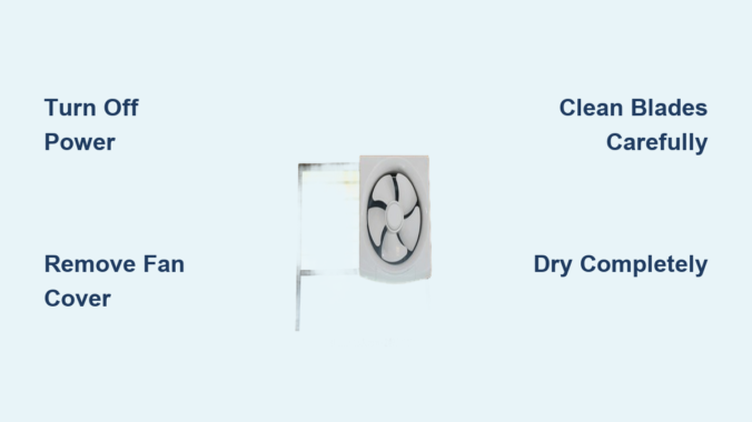
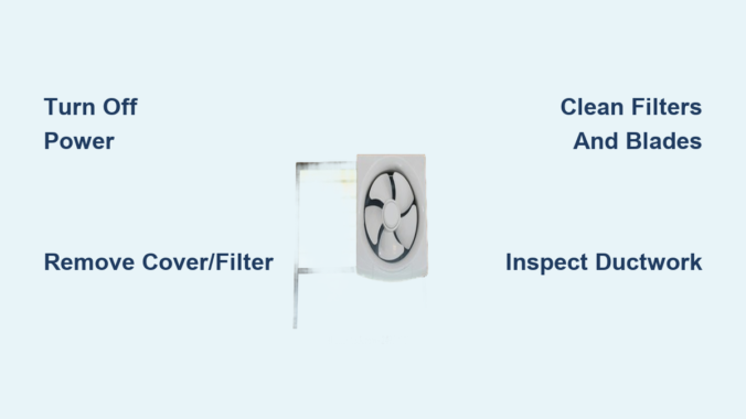
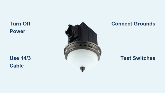
Safety First: Turn Off Power
:max_bytes(150000):strip_icc()/safely-turn-off-power-at-electrical-panel-1824677-02-7b71f4f489ab433e9932aa63771714fd.jpeg)
Before touching any part of the fan, eliminate electrical risk.
Cut Power at the Breaker
Flip the circuit breaker that controls the fan. While turning off the wall switch is a start, it does not guarantee the unit is de-energized. Cutting power at the panel ensures no accidental shock during handling.
Confirm No Live Current
Use a non-contact voltage tester near the fan housing or switch. If it beeps or lights up, double-check the correct breaker is off. Never skip this step even older fans can carry lethal current.
Wear Protective Gear
Safety goggles shield eyes from falling dust and debris. A face mask or respirator prevents inhalation of mold spores, dust, and allergens. Gloves protect hands from grime, especially in greasy kitchen hoods. Hair covering keeps hair out of moving parts and dust.
Gather Cleaning Tools and Supplies
Use the right tools to clean thoroughly without damaging the fan.
Essential Supplies
Warm (not hot) water and mild dish soap form the base of your cleaning solution. You will need microfiber cloths (both damp and dry) for wiping and drying. A soft-bristled brush such as an old toothbrush works perfectly for scrubbing tight spaces. Have a towel or absorbent mat ready to catch debris.
Cleaning Tools
A vacuum with brush and crevice attachments removes loose dust before scrubbing. A screwdriver is essential for removing screws or acorn nuts. Optional tools include compressed air for blowing dust from motor fins and a soft plastic scraper for stubborn buildup.
Avoid: Harsh chemicals like bleach, oven cleaners, or degreasers. They can warp plastic or corrode metal components.
Remove the Fan Cover Safely

Access begins with removing the cover carefully.
Identify Mounting Type
Most covers use one of three fasteners. Spring clips require gently pulling one side down, squeezing the clips, and releasing. Tabs need pressing inward while lowering the cover. Screws require a screwdriver to remove acorn nuts or fasteners.
Handle with Care
Set the cover on a soft towel to avoid scratches. If the unit has a light, disconnect wiring or remove the lens per manufacturer instructions.
Pro Tip: Note the cover is orientation. Some models have alignment marks. Match them on reinstallation.
Clean the Vent Cover Thoroughly
A dirty cover restricts airflow just as much as grimy blades.
Soak and Scrub
Fill a basin with warm, soapy water. Submerge the cover for 5 to 10 minutes to loosen grime. Use a toothbrush to scrub between louvers and along edges. Rinse under clean water, ensuring all soap residue is gone.
Dry Completely
Pat dry with a microfiber cloth or air-dry fully. Reinstalling a wet cover risks water dripping into the motor.
Warning: Never use steel wool, scouring pads, or abrasive cleaners. They scratch surfaces and trap more dirt over time.
Access the Fan Blades
Now reach the blades either by removing the assembly or cleaning in place.
Inspect the Interior
After removing the cover, look inside to identify the fan type. A squirrel cage (centrifugal) design is common in bathrooms with an enclosed structure and radial fins. An axial (propeller-type) design appears in older or kitchen units with exposed blades.
Remove the Fan Assembly If Possible
Locate one or two screws on the motor plate. Unscrew and gently lower the unit. Unplug any electrical connector if accessible.
Note: Some models do not allow full removal. If stuck, clean blades in place.
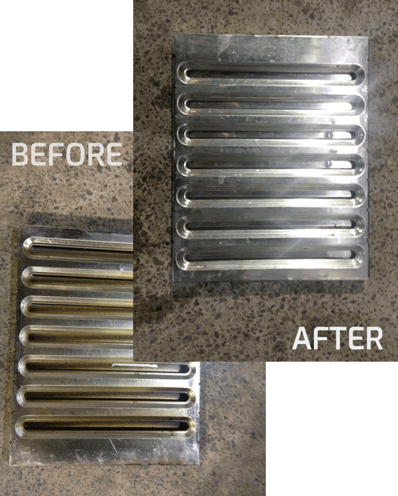
Clean the Fan Blades Properly
Tailor your method based on rotor accessibility.
Remove Rotor for Deep Cleaning
If the fan has a C-clip, snap ring, or setscrew, remove the fastener from the motor shaft. Slide the rotor off carefully. Soak in warm, soapy water for 10 minutes. Scrub between blades, along edges, and inside the hub with a toothbrush. Rinse and dry completely. No moisture should remain in crevices.
Never soak the motor or wiring. Only the plastic rotor can be submerged.
Clean Blades In Place
For fixed assemblies, vacuum first using a brush attachment to remove loose dust from blades and housing. Wipe each blade using a slightly damp microfiber cloth, rotating the fan by hand. Dip a toothbrush in soapy water for caked-on grime. Avoid wetting the motor. Never spray or drip liquid near electrical parts. Finish with compressed air or a dry brush to remove residue.
Goal: Restore smooth, balanced blades. Any warping or debris disrupts airflow.
Clean Internal Components and Duct
Do not stop at the blades. Clean the whole system.
Vacuum the Interior
Focus on the motor housing, wiring compartments (without touching wires), duct opening, and flapper valve if present.
Inspect the Flapper Damper
Ensure it opens when the fan runs and closes when off. Clean hinges and seals with a damp cloth to prevent sticking.
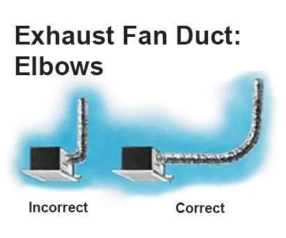
Check the Duct Connection
Confirm the duct is secure and kink-free. Look for mold, lint, or rodent nests. Clean accessible sections with a long-handled brush.
Clear the Exterior Vent
Go outside and remove leaves, nests, or ice blocking the cap. Ensure the backdraft damper moves freely. Confirm no pests have entered the duct.
Pro Tip: Clean the exterior vent annually even if the indoor fan looks fine.
Dry and Reassemble the Unit
Moisture is the enemy. Dry everything before reassembly.
Wipe and Air-Dry
Use dry cloths to remove surface moisture. If the motor got damp, wait 6 to 12 hours before powering on. Never rush this step. Water near wiring causes shorts.
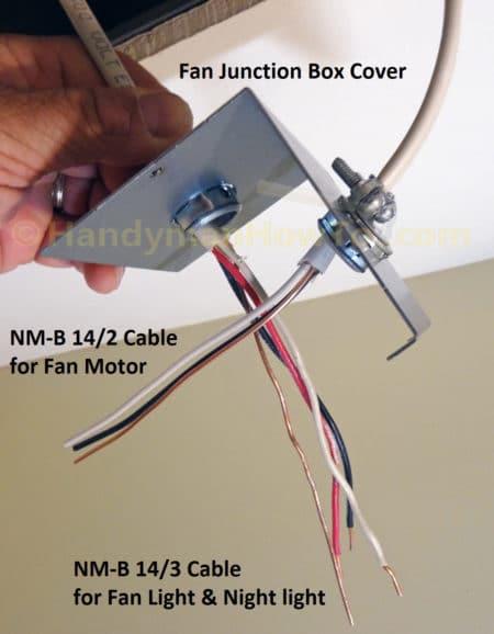
Reinstall the Fan Assembly
Slide rotor back onto the shaft if removed. Replace the C-clip or setscrew. Secure the motor plate with screws. Reconnect electrical plugs. Align and snap the cover back into place.
Check clearance: Ensure the cover does not touch the blades when spinning.
Restore Power and Test Operation
Final step: turn it on and verify performance.
Power Up Safely
Flip the circuit breaker back on. Turn on the fan at the wall switch.
Listen and Feel
Listen for strange noises. Grinding, buzzing, or scraping means misalignment or debris. Feel for strong airflow. Hold your hand near the vent. Air should feel brisk. Confirm smooth shutdown. Fan should stop completely when turned off.
Run for 5 to 10 Minutes
Let it operate to confirm stability. Many users report immediate improvements, quieter operation, faster steam removal, and no more foggy mirrors.
User Feedback: After cleaning a neglected fan, one homeowner said it sounds like a brand-new unit.
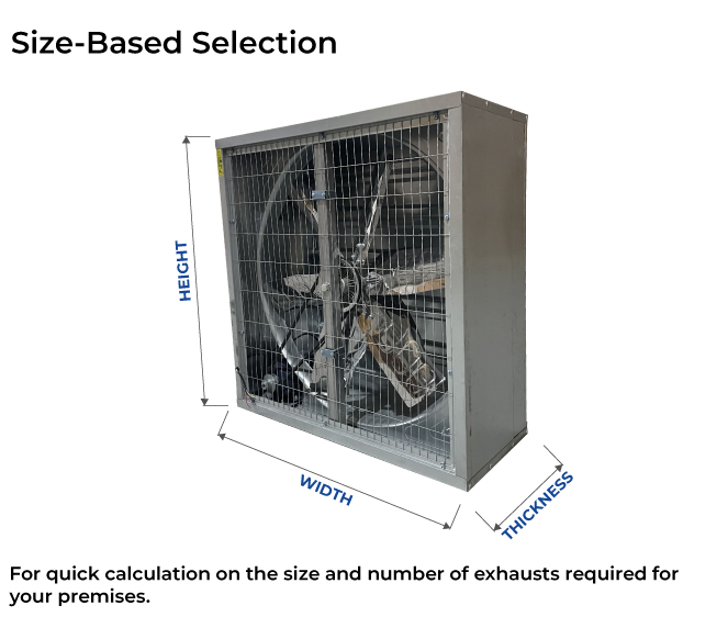
Measure Airflow to Confirm Results
Verify cleaning success with objective data.
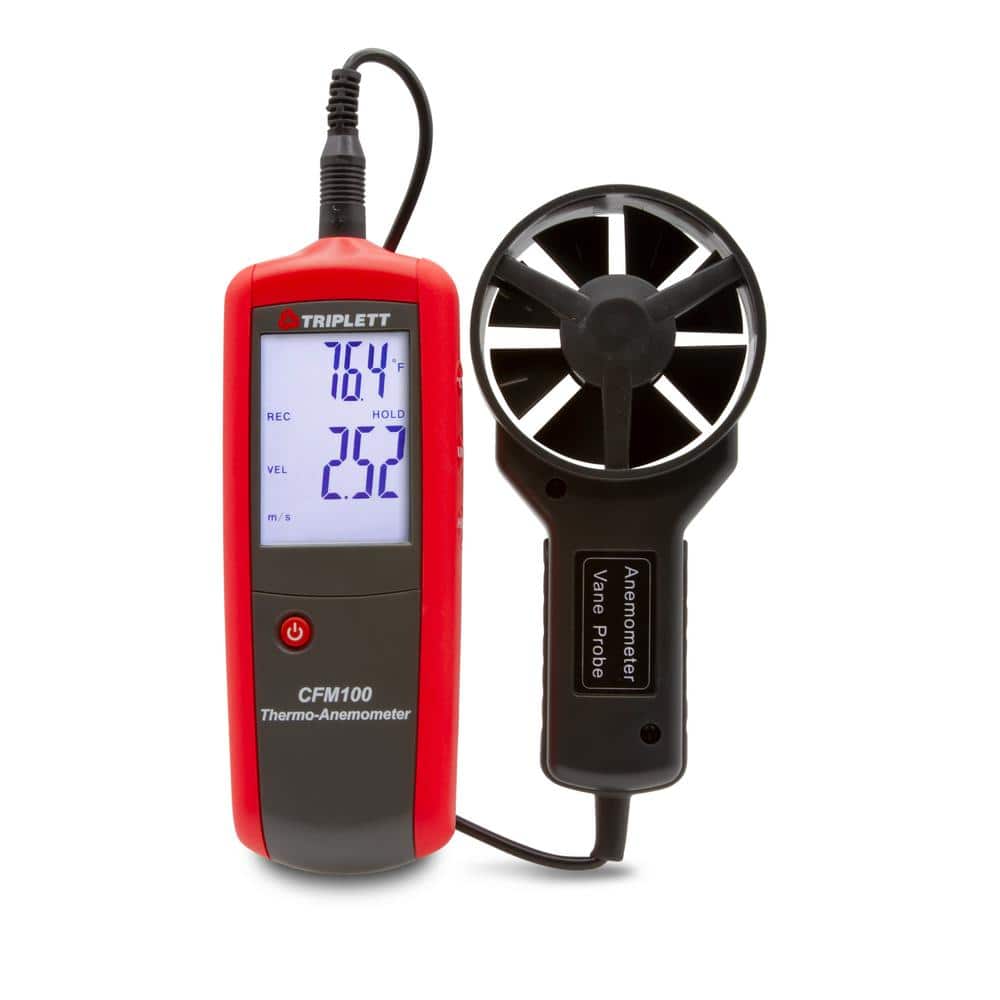
Use a Digital Anemometer
Hold it near the vent outlet. Record air velocity in feet per minute (fpm). Calculate CFM (cubic feet per minute) using velocity multiplied by duct area.
Compare to Rated CFM
Check the manufacturer label for the fan is rated airflow. If post-cleaning CFM is below 70%, the motor may be failing.
Note: Low-cost anemometers are not lab-accurate but work well for before and after comparisons.
Recognize When to Replace the Fan
Cleaning helps but not forever.
Replace If
The fan is still noisy after cleaning. Blades are cracked or warped. Motor won not spin or hums without starting. No steam removal occurs despite clean blades. Unit is 10 to 15 years or older. CFM remains low after maintenance.
Example: A 20-year-old fan replaced by an electrician in 30 minutes now clears steam in under a minute. Age matters.
Prevent Future Buildup with Smart Habits
Keep fans clean longer with simple routines.
Run Fan Strategically
In bathrooms, run during and 15 to 20 minutes after showers. In kitchens, turn on before frying or boiling and run 5 to 10 minutes after. Avoid leaving fans on unattended for hours. This reduces fire risk.
Schedule Regular Maintenance
High-use bathrooms need cleaning every 3 to 6 months. Kitchen internals need cleaning every 6 months (filters monthly). Low-use areas need cleaning every 1 to 2 years.
Pro Tip: Mark cleaning dates on a calendar or use a home maintenance app.
Avoid Harsh Chemicals
Stick to mild soap and water. Degreasers or bleach can degrade plastic, create fumes, or void warranties.
Know When to Call a Pro
Some jobs are best left to experts.
Call a Technician If
You are uncomfortable with electrical work. The fan is hardwired into a light fixture. Burning smell persists after cleaning. Ductwork is damaged or disconnected. Motor needs lubrication (if serviceable). Manufacturer recommends professional servicing.
Safety First: If you smell smoke or see sparks, shut off power and call an electrician immediately.
Real-World Cleaning Tips from Users
Homeowners share what actually works.
I Was Shocked by the Dust
One user placed a towel under the fan. Hundreds of dust clumps fell during cleaning. Always catch debris before it lands on your bathroom floor.
15 Minutes with a Toothbrush
Even if the cover looks okay, blades can be caked with hidden grime. Scrub thoroughly. Do not assume it is clean.
Finally Quiet
Multiple users reported dramatic noise reduction after cleaning fans neglected for 2 to 3 years.
Mirror Does Not Fog Anymore
Improved airflow means faster moisture removal. This is a clear sign the cleaning worked.
Key Takeaways for Cleaning Exhaust Fan Blades
Clean exhaust fan blades every 6 to 12 months (3 to 6 months in high-use areas) to maintain efficiency, safety, and air quality. Always cut power at the breaker before servicing. Use a vacuum, toothbrush, and damp cloth but never submerge the motor. Remove the rotor if possible for deep cleaning. Dry all parts completely before reassembly. Test airflow and noise after reinstallation. Replace the fan if it remains ineffective or damaged. Measure CFM for objective results. Inspect exterior vents annually. Label cleaning dates to stay on schedule.
Cleaning exhaust fan blades is not just about performance. It is about safety, air quality, and efficiency. A 30-minute job can prevent mold, reduce fire risk, and extend your fan is life by a decade. Make it part of your seasonal routine and breathe easier knowing your home is ventilation is working as it should.
Frequently Asked Questions About Cleaning Exhaust Fan Blades
How often should I clean my exhaust fan blades?
Cleaning frequency depends on usage. High-use bathrooms (daily showers) need cleaning every 3 to 6 months. Moderate-use bathrooms or kitchens need cleaning every 6 to 12 months. Low-use or guest bathrooms need cleaning every 1 to 2 years.
Can I use bleach or harsh chemicals to clean exhaust fan blades?
No. Avoid bleach, oven cleaners, degreasers, or solvents. These chemicals can warp plastic components, corrode metal finishes, create toxic fumes, or void warranties. Stick to mild dish soap and warm water.
What happens if I do not clean my exhaust fan blades?
Neglected fans accumulate dust, grease, and moisture. This reduces airflow by over 50%, strains the motor, increases fire risk, and degrades indoor air quality. You may notice increased noise, slow steam removal, musty odors, and mold growth.
Can I spray water directly on the fan blades to clean them?
No. Never spray water or cleaning solutions directly into the fan housing. Do not allow liquid to pool near electrical components. Use a damp cloth for wiping and avoid saturating the motor. Moisture near wiring causes short circuits.
How do I know if my exhaust fan needs replacement instead of cleaning?
Replace the fan if it remains noisy after cleaning, blades are cracked or warped, the motor won not spin or hums without starting, steam removal is ineffective despite clean blades, or the unit is over 10 to 15 years old with low CFM readings.
Do I need special tools to clean exhaust fan blades?
No special tools are required. Basic supplies include warm water, mild dish soap, microfiber cloths, a soft-bristled toothbrush, a vacuum with brush and crevice attachments, and a screwdriver for removing the cover. Optional tools include compressed air and a soft plastic scraper.
:max_bytes(150000):strip_icc()/safely-turn-off-power-at-electrical-panel-1824677-07-b4810db6af594101ac2be9f68a2f09d5.jpeg)


:max_bytes(150000):strip_icc()/How-to-Clean-a-Dusty-Bathroom-Fan-8419-09-bea27a1488e644e1988768fe60b67eb1.jpg)